LED line PRIME BACKLIT panels with ENEC certificate!
LED line PRIME BACKLIT panels have been awarded the prestigious ENEC certificate, awarded by the renowned institution TÜV Rheinland.
Check what the individual markings on the products mean. Thanks to our guide, you will find out which LED lamps will be right for you. We encourage you to read the materials.
„Flickering can be defined as: the perception of visual instability/unsteadiness caused by lighting variations in brightness”.
Research has shown that flickering has an adverse effect on human well-being and causes tearing and eye fatigue. Currently, two flicker parameters have been developed by the IES. “Flicker Percent” which is featured by relative measure of cyclic variation in light amplitude and “Flicker Index” which includes the percentage of flicker, the shape of the waveform and the work cycle, which refers to the percentage of time in a single cycle.
In addition to flickering, we distinguish a separate stroboscopic effect, also called SVM (Stroboscopic Visibility Meausure). The SVM is a method used to quantify the stroboscopic effect visibility in general illumination application. SVM is defined by measuring the visibility threshold of light waveforms modulated at several frequencies and uses Fourier analysis to convert the wavelength shape of the light intensity. The stroboscopic effect can cause an impression of slowness, stopping or even reversal of the direction of movement of an object, which can lead to various accidents. The frequency amplifying the unwanted stroboscopic effect is between 80 Hz and 2kHz. In addition, stroboscopic effects can cause epilepsy, loss of perception and headaches.
At the LED line® Light Research and Measurement Centre, in addition to working towards elimination of flickering, we conduct continuous research on the negative impact of undesirable phenomena in lighting which it can have on health. As a manufacturer of lighting, we educate end users on the health aspects of artificial lighting through information campaigns and training.
Scientific research has shown that a person should spend several hours a day in light of 4000 lux in order for the body to function properly. If we are exposed to insufficient amount of light we can experience a significant decrease in concentration and become tired and feel a sense of sleepiness. What’s more, a person may fall into depressive state in the longer absence of exposure to natural light.
Artificial lighting is also not neutral to humans. The colour of artificial light can affect the mood, level of concentration and psyche of a person. The colour of the light is expressed by the colour temperature in kelvins (K). It is commonly believed that white colour light with a warm tint (below 3300 kelvins) gives a sense of comfort and relaxation. The neutral colour (4000 kelvins) works well in offices as it boosts up our concentration. On the other hand, the colour temperature of approximately 6000 – 6500 kelvins is considered to be comparable to the daylight (on a cloudless day).
LED lighting: tailor-made colours
LED line® offers a wide range of lighting solutions out of which we can choose the right color temperature to suit our needs. LED line® lamps offer a wide range of colour temperatures from 2700K to 6500K.
In turn, among the LED line® strips you can choose from among those with a color temperature of 2400K to 13000K. Particularly, MULTIWHITE™ strips are unique in their construction as these solutions offer various tints of white colour. You can set any tint from cold to warm (3200 – 7000 Kelvins).
A significant parameter which is often overlooked by less experienced investors is the quality of illumination emitted by a luminaire – unified glare rating. The lower the UGR, the higher the comfort of people working within the illumination range of the luminaire. It is obvious that the greater the comfort, the higher the productivity of the employees.
Converting the UGR impact into quantifiable numerical values would be extremely time-consuming, but already at this stage it is possible to answer the above question in the affirmative manner. Yes, high-performance lighting increases employees’ productivity. That is why it is worth choosing luminaires with a low glare rating for the professional illumination of offices.
The photobiological safety PN-EN 62471 norms outline the main four risk groups:
Over and above, the norms make mention of the actual risks caused by both, natural and artificial light. These are inter alia:
When analysing the above hazards, it is becoming obvious that any sources of light shall be purchased from trusted manufacturers only.
50,000 hours means 5.7 years lifespan on the assumption that the light is switched on 24 hours a day; 7.6 years if the light is switched on 18 hours a day and 11.4 years if the source is switched on 12 hours a day.
The use of professional LED lighting is means predominantly energy-costs saving, comfort of use and protection of the environment. Below is a short list of advantages of using LED lighting:
As commonly accepted, LED product lasts four times as long as a compact fluorescent lamp and 25 times as long as a conventional incandescent lamp that generates the same amount of light.
LED light sources have a longer life span, which reduces their maintenance and replacement costs . Since LED products need to be replaced less often, the user spends less time on buying new lamps and replacing them. LED light sources consume less energy than conventional light sources. Investment pays for itself quite quickly.
An increase in power in watts translates into a slight decrease in efficiency. A 3W LED light source will emit slightly less light than three 1W light sources. In general, the characteristics of components (e.g. optics, heat sink, chips, LED modules and driver) have a greater impact on the light output than the wattage output.
Some types of lighting can cause tiredness, create a sense of relaxation or deliver a sense of energy. In order to describe the colour of light we shall focus on the colour temperature measured in Kelvin SI unit.
Here is a brakdown of LED lighting according to the color temperature scale (CCT):
Each lighting system using LED strips requires a power supply with appropriate amount of power for proper functioning.
NOTE: In order to ensure durability of the LED lighting system, it is necessary to choose the wattage of the power supply which is at least 10% higher than the required power for the given section of LED strip. This guarantees that the PSU will not be overloaded, which translates into its durability and reliability.
The below tabel should help you to choose the appropriate PSU for your LED strip:
Type of LED Strip: | 300 LED | 150 LED | 600 LED | 300 LED 5630 | 300 LED |
|---|---|---|---|---|---|
Power of PSU | (4,8W/mb) | (7,2 W / mb) | (9,6 W / mb) | (18 W / mb) | (14,4 W / mb) |
15 W | 2,8 mb | 1,8 mb | 1,4 mb |
| 0,9 mb |
18 W | 3,3 mb | 2,2 mb | 1,6 mb |
| 1,1 mb |
20 W | 3,7 mb | 2,5 mb | 1,8 mb | 1 mb | 1,2 mb |
30 W | 5,6 mb | 3,7 mb | 2,8 mb | 1,5 mb | 1,8 mb |
36 W | 6,7 mb | 4,5 mb | 3,3 mb | 1,8 mb | 2,2 mb |
45 W | 8,4 mb | 5,6 mb | 4,2 mb | 2,2 mb | 2,8 mb |
60 W | 11,2 mb | 7,5 mb | 5,6 mb | 3 mb | 3,7 mb |
80 W | 15 mb | 10 mb | 7,5 mb | 4 mb | 5 mb |
100 W | 18,7 mb | 12,5 mb | 9,3 mb | 5,0 mb | 6,2 mb |
120 W | 22,5 mb | 15 mb | 11,2 mb | 6,0 mb | 7,5 mb |
150 W | 28,1 mb | 18,7 mb | 14 mb | 7,5 mb | 9,3 mb |
200 W | 37,5 mb | 25 mb | 18,7 mb | 10 mb | 12,5 mb |
The above table takes into account the necessary power reserve of the PSU
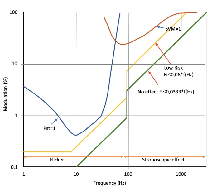
The flicker free label can be applied to a product on the basis of three separate measurements taken using GL Spectis 1.0 + flicker equipment supplied by the GL OPTIC brand.
Flicker index: its value shall be below 0,1.
Flicker percent: it value shall be below 0,0333 x Hz (flicker frequency).
The above conditions to be satisfied are suggested by the IEEE organization , known as: “no observable effect level”.
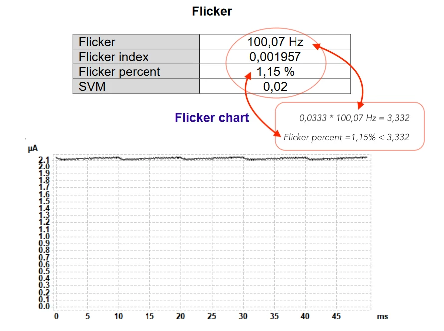
Example of how to calculate the flicker value based on a selected Flicker report.
SVM (stroboscopic visibility measure) must below 1.
If all three conditions are fully satisfied, the device is labelled “flicker free“.
In terms of design and functionality, power supply methods can be divided into three main groups:
Each of them serves exactly the same purpose – it directly connects the power network to the LED structure and provides it with conditions for correct operation. It also determines the main parameters of the whole lamp. On the power supply depends, among other things, the level of PF coefficient and the stroboscopic effect.
Here is a summary of the most important properties of each group:
It is a power supply with a very simple structure. However, this is one of its few advantages. Its disadvantages certainly include a very low Power Factor coefficient and very low efficiency. There is also no possibility to modify such a power supply in order to eliminate the stroboscopic effect. Due to the considerable size of the power supply and successively improved eco-design regulations concerning the PF factor, it is used in low-power lamps, usually up to 3W.
This type of power supply contains semiconductor components in its structure. However, it is still a simple construction. The use of an IC element significantly reduces the size of the entire power supply, and significantly increases the PF factor, as well as the efficiency. An additional advantage of this design is maintaining good output parameters, which in turn increases the life of LEDs. Still, the lamp provides an unacceptable level of strobe effect, which, however, can be reduced by slightly changing the structure, but at the expense of the Power Factor. So, this entails either a stroboscopic effect and good PF, or a stable light without flickering but with a lower phase shift factor. Power supplies of this type are used in low power lamps, where the most important thing is to achieve minimum lamp size.
This type of power supply is a much more sophisticated structure. Thanks to the application of new technologies, we can obtain the advantages of such a solution. The main advantages include:
Taking into account the high requirements for all LED line® sources, the vast majority of the brand’s sources use switched-mode power supplies, which take over all their advantages – very good optical and electrical parameters, while maintaining the highest safety standards.
All MR16 and MR11 LED Line ® brand sources have switched -mode power supplies incorporated. They provide stabilization of LED working points, significantly increasing the life of the lamp. They also provide a constant level of luminous flux within the whole range of supply voltage. What is a great advantage of this type of source, is also the reason why we cannot use PWM type power supply.
The LM79-08 is an IESNA approved standard for the measurement of complete luminaires at the LED line® Light Research and Measurement Centre. It guarantees uniform and correct measurements of light and electrical parameters. Using the LM79-08 standard, we are confident that the measurements are always taken under the same conditions and that the compatibility of the measurements is the same in all laboratories.
The testing methodology included in the standard specifies both electrical and photometric measurements carried out under specific conditions and parameters. At the LED line® Light Research and Measurement Center photometric measurements are performed in Ulbricht integrating sphere in accordance with the LM79-08 standards, which requires measurements of the total flux of light, CRI color characteristics, CCT, chromaticity coordinates, electrical parameters and light efficiency. During the measurements it is necessary to ensure the tests are performed in an ambient temperature of 25°C with a tolerance of +/- 1°C and to limit the air movement during the measurements. The AC power supply must provide a harmonic distortion limit of 3%. In addition, measurements should start after the luminaire has been warmed up for 30 minutes. LM79-08 standard also refers to measurements in gonio spectrometer, where additional measurement of light distribution is performed.
A separate LM80-08 – standard – is used for LED light sources without built-in power supplies. According to its requirements, the luminous flux and chromaticity coordinates must be measured at three levels where the temperature of LED/housing connection reaches: 55°C, 85°C, and the third temperature value is specified by the LED manufacturer. Measurements are made for a period of min. 6000 hours with intervals of no more than 1000 hours. The results of the measurements allow to observe how the diode changes its light parameters during the test. Please note that the LM80-08 standard only provides a method for testing the maintenance of the luminous flux.
Estimation of LED source durability/degradation is provided by TM21-11, which uses the LM 80-08 test standard. Based on the test, estimation of light flux loss during 36,000 hours (6k) (or longer if the test is longer than minimum) is made. The test result is recorded as e.g. L70, where 70 means that the LED will maintain a luminous flux of 70% of the initial value after a period of 36,000 hours (6k).
In summary, it should be remembered that the LM79-08 standard applies to complete luminaires and light sources equipped with power supply systems. LM80-08 tests are performed on a single LED or a set of LEDs without power supply systems in order to determine the loss of light flux by using calculations determined in TM21-11 document.
MacAdam’s ellipses show the areas shown in the chromaticity diagram. They are defined in MacAdam steps, indicating colour temperature differences. It is assumed that the differences in colour temperature of LED sources falling within step 3 are indistinguishable by most people.

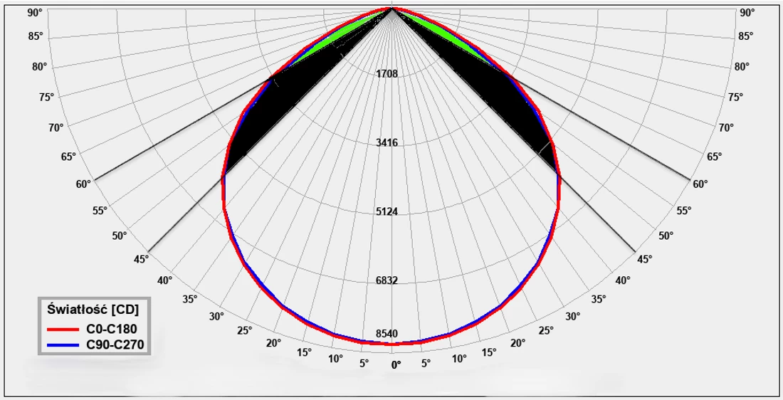
These represent the light distribution produced by a luminaire or light source after measuring its light intensity in different directions. A curve (diagram) of the luminaire’s light intensity can be created after converting the results into values, which would be obtained using light sources with a total luminous flux of 1000lm.
The graph shows light distribution in two planes:
These are defined as shown in the figure below. If the luminaire is rotationally symmetrical, the light distribution is given in one plane C only. However, in the case of an unsymmetrical luminaire, the luminous values are given in planes C in angles of 30° or even 15°. The light distribution diagram provides basic information about the shape of the luminaire’s light distribution.

Position of the coordinates on the chromaticity diagram in relation to the Planck curve. The parameter determines the distance from the Planck curve.

Measured in the range between 0 and 100, this is a quantitative measure of the ability of a light source to reveal the colours of various objects faithfully in comparison with an ideal or natural light source. Numerically, the highest possible CRI value is 100 and would only be given to a source identical to standardised daylight (sunlight with a colour temperature of 6670K). The higher the CRI value, the better the colours of illuminated object/surface are revealed. Ra is the average value of 8 colour samples, whereas CRI uses a palette of 15 colours (R1 – R15) and tends to be more accurate.

Beam angle of a directional light source is another light sources’ parameter which is normally provided by lighting manufacturers.
This parameter determined based on the light’s intensity in a certain direction. The analysis begins from “angle zero” – in front of the luminaire. We check the luminous intensity levels by increasing the angle and when we observe that the luminous intensity level is twice as low as its maximum, we consider this as the borderline for the beam angle measurements.
This is a photometric measure of the luminous intensity per unit area of light travelling in a given direction. It describes the amount of light that passes through, is emitted from, or is reflected from a particular area, and falls within a given solid angle. The SI unit of luminance is ‘candela per square metre’ (cd/m2).
This shall not be confused with Luminance. Illuminance is a measure of how much the incident light illuminates the surface: 1m2 (lm/m2), wavelength-weighted by the luminosity function to correlate with human brightness perception. The SI unit is Lux.
A batch file dedicated for the design software (e.g. Dialux, Relux) – these files are necessary for the creation of lighting design. It describes the intensity of light in the individual points of a sphere grid. These files also contain information on the geometry of the light output to the outside of a luminaire. The files are featured by the *.ies extension defined by IESNA LM-63-2001 and *.ldt defined as EULUMDAT.
Luminous efficacy is a measure of how well a light source produces visible light. It is the ratio of luminous flux to power, measured in lumens per watt (lm/W) in the International System of Units (SI).
This is the ratio of luminous flux (a percentage of light output) emitted by the luminaire to the light output emitted by its lamps (sources of light) η = Φ opr./Φ.
This is the measure of the perceived power of light. The SI unit of luminous flux is Lumen (lm).
Useful luminous flux (Φuse), means the part of the luminous flux of a light source that is considered when determining its energy efficiency:
Expressed in Kelvins [K], it is a measure of the colour impression of a given light source. Lower [K] values are perceived by the human eye as warmer colours.
Flickering can be defined as: the perception of visual instability/unsteadiness caused by lighting variations in brightness. The Illuminating Engineering Society (IES) developed two flicker metrics.
Percent Flicker – A relative measure of the cyclic variation in the amplitude of a light in one on/off cycle (index range: 0%-100%). 100% flicker would indicate that, at some point in the cycle, there is no illumination provided at all. In a properly stabilised light source, the Percent Flicker parameter will be 0%.
Flicker Index – This includes the flicker percentage and two other variables: the shape of light intensity waveform or output light distribution curve. In another words, it is a measure of the cyclic variation taking into account the shape of the waveform.. The lower the flicker percentage and flicker rate, the better the stability of a light source.
The Pst Lm indicator measures the flicker of visible light caused by modulation in the frequency range from 0.3 Hz to 80 Hz.
A value of Pst Lm =1 means that an average observer has a 50% probability of detecting the flicker.
IEEE Standard 1798™️-2015
The SVM is a method used to quantify the stroboscopic effect visibility in general illumination application. SVM is defined by measuring the visibility threshold of light waveforms modulated at several frequencies and uses Fourier analysis to convert the wavelength shape of the light intensity. The stroboscopic effect can cause an impression of slowness, stopping or even reversal of the direction of movement of an object, which can lead to various accidents.
An uncomfortable and undesirable state of the vision, defined as the sensation of dazzling light caused by excessive brightness level in the field of vision. UGR is not a stand-alone technical parameter of a luminaire, it only indicates which UGR rating can be achieved in a lighting design with a given luminaire.
This is the electromagnetic spectrum with wavelength from 100nm to 400nm, shorter than that of visible light but longer than X-rays. By reason of the extent (scale) or effects of the UV presence, the UV is divided into the following:
Over 95% of the UV radiation reaching the earth is UV-A, the rest of the radiation is retained by the earth’s atmosphere.
LEDs do not emit UV radiation so the technology is safe not only for living organisms but also for various elements, such as paints, colorful plastics, museum exhibits.
In alternating current circuits, reactive power is a quantity describing the fluctuations of electric energy between the elements of an electric circuit. This oscillating energy is not converted into usable/effective energy or heat, but is necessary for the functioning of electrical equipment. The energy is taken from the source in one part of the alternating waveform period, stored by the receiver and returned to the source in the other part of the period, which is related to the disappearance of the magnetic field in the receiver. For sinusoidal waveforms, reactive power is defined as the multiplication (product) of induced voltage and current values, and the phase shift angle sinus between voltage and current. The reactive power SI unit is var (var).
Q=U*I*sinᶲ
In AC systems, this is the part of the power that the receiver takes from the source and changes to effective energy or heat. In DC systems, all power is active power. The SI unit of active power is watt (W)
P=U*I*cosᶲ in AC systems
P=U*I in DC systems

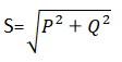
Apparent power is the product (multiplication) of the RMS (root mean square) values of the current and voltage in AC circuits.
S=U*I
The apparent power SI unit (S) is the Volt-Amp (VA). Apparent power is closely related to reactive and active power.
This relationship is represented by the formula and the power triangle.

The power factor of an AC electrical power system is defined as the ratio of the active power absorbed by the load to the apparent power flowing in the circuit. In simple terms, it determines what part of the energy taken from the electrical network will be used effectively by the device. A power factor of less than one indicates that the power was consumed from the electrical network but not used (reactive power). This causes undesirable heat emission.
The table shows the permitted PF values depending on the electrical power of the LED lamps
Functionality parameter | Requirement as from stage 1, except where indicated otherwise |
Lamp power factor (PF) for lamps with integrated control gear |
|
COMMISSION REGULATION(UE) NR 1194/2012
This is a system in which by controlling input voltage the user adjusts the output power level of the device. The control voltage is independent of the device power supply voltage. The value of 10V corresponds to 100% of the output power. The value of 1V corresponds to 5-10% of the output power.
This is a digital addressable interface dedicated for lighting control devices. The DALI interface’s technical standards are set out in IEC 60929 E4 document. This is a widely available standard for lighting control devices created by the leading lighting manufacturers. It is a two-way dimming interface with a master-slave structure. Information flows from the controller, which acts as a master, to the control units (DALI controllers), which only act as slaves. The digital signals are transmitted via a standard two-wire cable. These control wires can be negative and positive polarised, although most DALI controllers are designed to be neutral. The DALI system is configurable by using dedicated software. With the use of DALI system, the user may create up to 16 configurations addressing up to 64 devices without the need for rewiring.

This is a digital interface for lighting control devices, in particular – this is a dedicated solution for dynamic lighting. The system can be addressed with 512 channels in one signal line with up to 32 devices. The DMX technical standards are set out by USITT organisation and has become a widely used system within the music/movie stage industry or for the professional illumination of various buildings. Signal receivers are controlled by a shielded two-wire cable with an impedance of 110 ohm. The control is performed with the use of DMX standard controllers.
This is a lighting concept in which the human and their needs are put at the centre of lighting design. All human beings have evolved with natural light so the composition of the sunlight spectrum is the best model on which to base our lighting design. Lighting, according to the HCL concept, imitates the parameters of natural light and adapts them to the daily needs of a human. That means that light designed according to HCL should give us energy to work in the morning and prepare us for a period of relaxation and sleep in the evening.
This is a method of controlling and regulating electric current or voltage signal of constant amplitude and frequency by changing the value of the current or voltage fed to the load. The average value of voltage (and current) fed to the load is controlled by turning the switch between supply and load on and off at a fast rate. The longer the switch is on compared to the off periods, the higher the total power supplied to the load.
Phase control dimming systems alter the light intensity by altering the supply voltage. The power supply voltage is altered by cutting off the leading or trailing edge. This means of control is performed without an additional control wire. The user shall simply connect the dimmer in series between one of the mains wires and the receiver (equipment). We must remember about the compatibility of light sources (driver, LED module) with this analog dimmer.
For LED receivers it is more appropriate to use RC type of dimmers dimming the trailing edge. Impact current is small and grows relatively slowly.

For RL loads it is generally more appropriate to use dimmers cutting off the leading edge.

An intelligent system designed for controlling devices via WiFi and/or Bluetooth. This is an integrated automation environment controlled by Smart Life or TuyaSmart application. Thanks to devices equipped with the Tuya module, a person can easily manage your own apartment, not only while staying there, but also at a distance, without having to make big changes to the electrical installations.

Artificial light systems which also use daylight are striving to balance the amount of electrical light needed for appropriate area illumination to reduce the power consumption. It can be done with light control techniques that can dim or switch the electric light in response to changing amount of daylight.
The IK rating is an international numeric classification to indicate the degrees of protec-tion provided by light fixtures against external mechanical impacts. It provides a means of specifying the capacity of a fixture (luminaire) to protect its parts (components) from external impacts. The range of protection is measured on the scale from 00 (no protection) up to 10 (impact resistance against 20J). The higher the numerical value of the IK parameter, the greater the mechanical protection of the given device.
IK rate | Impact energy | Impact equivalent |
|---|---|---|
| 00 | 0J | no protection |
| 01 | 0,15J | impact of a 200g mass dropping from 7.5cm height |
| 02 | 0,20J | impact of a 200 g mass dropping from 10cm height |
| 03 | 0,35J | impact of a 200 g mass dropping from 17,5cm height |
| 04 | 0,50J | impact of a 200 g mass dropping from 25cm height |
| 05 | 0,70J | impact of a 200 g mass dropping from 35cm height |
| 06 | 1J | impact of a 500g mass dropping from 20cm height |
| 07 | 2J | impact of a 500g mass dropping from 40cm height |
| 08 | 5J | impact of a 1700g mass dropping from 29.5cm height |
| 09 | 10J | impact of a 5000g mass dropping from 20cm height |
| 10 | 20J | impact of a 5000g mass dropping from 40cm height |
IP protection class classifies and rates the degree of protection provided against ingress of body parts, solid objects, dust, water or other liquids to the inside of the luminaire. Depending on the degree of protection, the device may be dedicated to work in various conditions. This table below shows what each digit or part of the IP code represents.
First digit: protection against the ingress of solid objects (according to PN-EN 60529: 2003)
Protection level
0 – no protection
1 – protection against contact with hazardous parts with a back of a hand protection against solid objects with a diameter of 50mm or more
2 – protection against contact with hazardous parts with a finger protection against solid objects with a diameter of 12.5mm or more
3 – protection against contact with hazardous parts with tools, tick wires, etc. protection against solid objects with a diameter of 2.5mm or more
4 – protection against contact with hazardous parts with most wires, slender screws, etc. protection against solid objects with a diameter of 1mm or more
5 – protection against contact with hazardous parts with wires dust protected – ingress of dust not entirely prevented (some ingress shall not have a harmful effect on the operation of the luminaire)
6 – protection against contact with hazardous parts with wires dust tight – full protection against ingress of dust
Second digit: protection against the ingress of liquids (according to PN-EN 60529: 2003)
Protection level
0 – no protection
1 – protection against water drops
2 – protection against water drops when tilted at 15° (vertical dropping shall have no harmful effect on the operation of the luminaire)
3 – protection against spraying water at any angle up to 60° from the vertical
4 – protection against splashes of water from any direction
5 – protection against a water jet (12.5 litre per minute) poured onto the housing from any direction
6 – protection against a powerful water jet (100 litre per minute) poured into the housing from any direction
7 – protection against the short immersion in water (30 minutes up to 1m of submersion)
8 – protection against the continuous immersion in water (housing permanently submerged in water as per the conditions agreed between the producer and the user, but the depth should be greater than at IP7 above)
9 – protection against powerful high temperature and high pressure water jets (80-100 bar and temperature + 80° C) in accordance with DIN 40050
Additional letters (according to PN-EN 60529: 2003)
Letter Degree of protection
A – protection against access to dangerous parts with the front of hand
B – protection against access to dangerous parts with a finger
C – protection against access to dangerous parts with a tool
D – protection against access to dangerous parts with a wire
Supplementary letters (according to PN-EN 60529: 2003)
Letter Meaning
H – high voltage equipment
M – device moving during water test
S – device standing still during water test
W – Device is suitable for use under certain weather condition
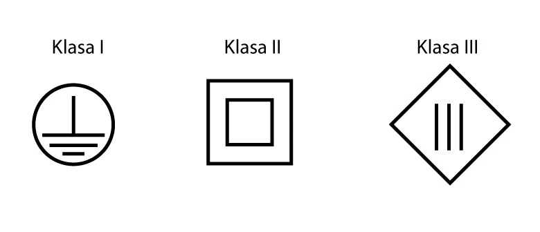
This is an international standard set up by the International Electrotechnical Commission defining the protective-earth connection requirements for electronic devices. In other words, the protection class defines the means that should be adopted to ensure protection against electric shock. However, it is not in any extent a measure relating to the safety of the given product. The classification is set out in the PN-EN 61140: 2005 regulations. In summary, there are four classes of protection: 0, I, II, III. Protection classes are illustrated with symbols, except for protection class 0, which has no symbol and therefore no protective earth connection whatsoever. The symbols are shown in the below picture.
Due to the increasing need to save electricity, the use of LED sources has become a necessity. So the long lifetime of LED modules brings both environmental and financial benefits. Due to the need of determining the durability of LED sources, a parameter marked LxBy was created. This parameter indicates the time in hours after which 50% of a population of LEDs parametrically reduced their lumen output, in a gradual way, and provides less than 70% of lumen output compared to the initial (original) luminous flux. A luminous flux lower than the lumen maintenance factor (expressed by Lx value) is called a “parametric failure” because the product produces less light, but remains working. By way of illustration, the life span marked as L70B50 50000h tells us that after a period of 50000 hours, 50% (B50) of a population of LEDs (which a given LED lamp is equipped with) provide up to 70% (L70) of the initial light output. Due to the fact that the temperature has a significant influence on the Lumen Maintenance Factor(Lx) it is necessary to give indication for the ambient temperature at which the life span of LxBy was determined. As the temperature has a significant impact on LxBy’s lumen maintenance factor, the ambient temperature at which LxBy’s shelf life is determined should be given.
Amount of Cu (copper) used in the production of PCB laminate. Copper is a very good conductor of heat and electricity. The greater amount of copper used on the laminate guarantees higher voltage and current stability as well as thermal resistance, which allows for the longer life span of LED light sources..
This is also known as acrylic glass – material used for the production of lamps’ covers and diffusers. This material is highly resistant to UV radiation which prevents the diffusor from yellowing (the diffusor remains pure white for many years of use) . It also has a very good visible light transmission of 92%. The material is also easily recyclable.
Material used in the construction of LED luminaires. It has an excellent mechanical properties and is particu-larly resistant to mechanical impact. Compressive strength is similar to aluminium. Visible light transmission is at 90%.
Type of safety glass processed by controlled thermal or chemical treatments to increase its strength compared with normal glass. It is used in the production of lampshades and diaphragms in LED fittings. It has three times greater resistance to mechanical damage compared to ordinary glass. Tempered glass has much higher thermal resistance than standard glass and, when broken, the glass crumble into small granular chunks instead of splintering into jagged shards as plate glass.
LED line PRIME BACKLIT panels have been awarded the prestigious ENEC certificate, awarded by the renowned institution TÜV Rheinland.
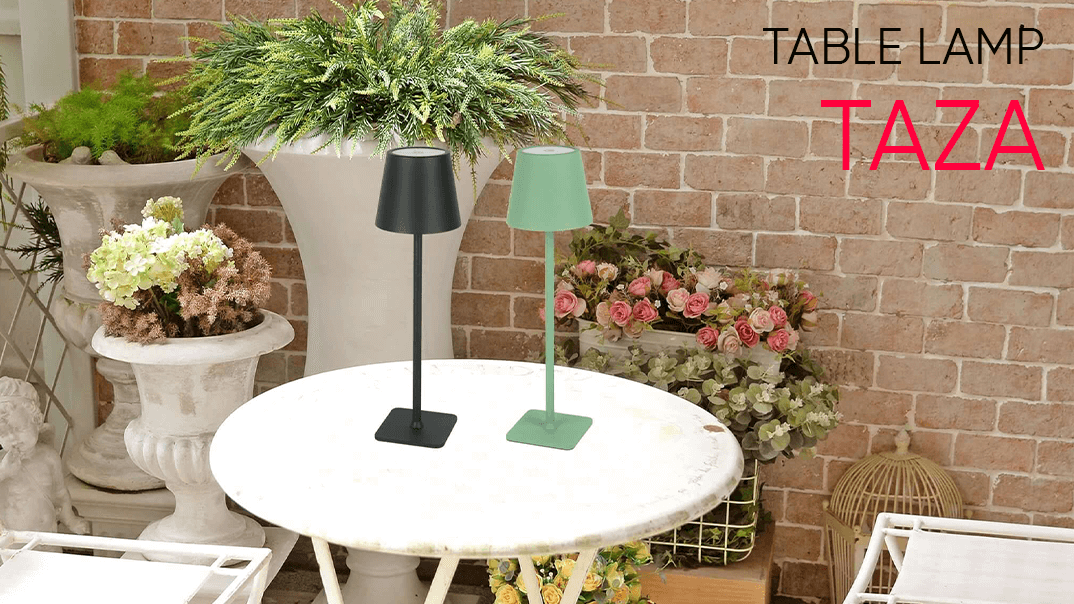
An innovative, wireless table lamp. Despite its compact size, it will surprise you with its numerous functions. This is a perfect lamp for people who value timeless style and functionality.
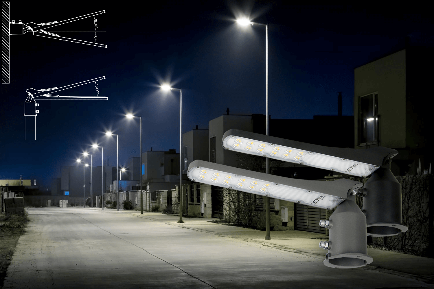
FLAMINGO outdoor luminaire is a versatile solution with a wide range of applications in outdoor lighting in various spaces such as roads, parks, parking lots and backyards.
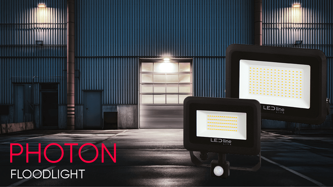
LED line LITE PHOTON floodlight is a solution that saves up to 90% of energy compared to standard light sources. At the same time, the new model provides even higher luminous effciency – at 100 lm/W!
If you are looking for opportunities to develop your business, we have a specific proposition for you: we invite you to join us as a partner cooperating with our distribution networks.
Why LED line?
Because we are an ambitious, dynamic company that is gaining recognition both on the Polish market and internationally. We are a team of experts who create partnership-based business relationships based on trust. We operate based on the win-win principle, and our efficiency-based approach ensures a higher level of profit.


Our offer is addressed to both large purchasing groups as well as small shops specializing in the sale of lighting products.
More

LED line is one of the few lighting companies in Poland with such an extensive and modern technological base that allows us to support developers and investors in the implementation of advanced investments.
More

We work with respected installation companies operating throughout Poland. Our specialists train employees in the field of industrial and commercial lighting installation.
More